TABLE TOP ASSEMBLY
Prerequisites
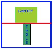
Figure 1. DO NOT TAKE THE TABLE BEYOND THE MARKED LINE
Procedure
- Turn the system power ON. Refer to Lockout / Tagout for System Cabinet PDU Main Breaker.
- Disconnect the Table from MR Magnet; take it out from the Magnet
room. Refer to TAKE TABLE OUT FROM THE MAGNET ROOM
- Remove the scissor covers from the table. SCISSOR COVERS
- Remove the Cradle from the Table. Refer to Posterior Array Coil Replacement with removing Fixed Table.
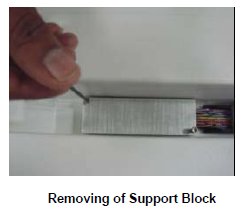
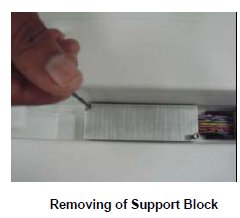
- Remove the Support block fixed to the tabletop for the cables.
Figure 2. Support block
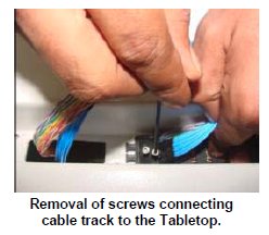
- Remove the Cable tract connecting screw to the table top.
Figure 3. screw
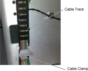
- Remove the cable cramp and track and remove cables.
Figure 4. Cable cramp and track
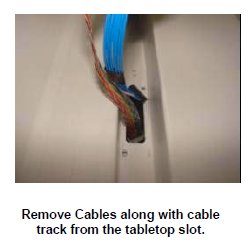
- Remove the Cable assemblies along with the cable tract from
the Tabletop.
Figure 5. Cable assemblies
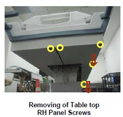
- Remove the Table Top RH Panel fixing screws in the Table.
Figure 6. Table Top RH Panel fixing screws
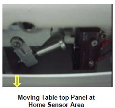
- Bent down the right panel slightly. Do not apply any pressure
which bents down the Panel.
Figure 7. Bent down the right panel slightly
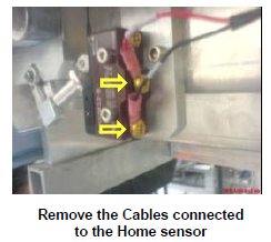
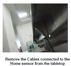
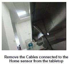
- Remove the cables connected to the Limit switch of the home
sensor.
Figure 8. Remove the cables
- Remove the Home sensor Cable assembly from the Tabletop.
Figure 9. Home sensor Cable assembly
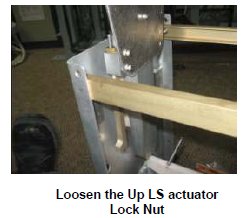
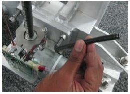
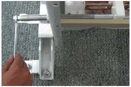
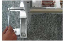
- Loosen the Up LS actuator lock nut with the help of 7/16 spanner.
Figure 10. Loosen the Up LS actuator lock nut
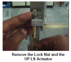
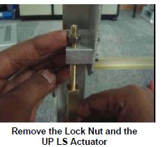
- Remove the Up LS actuator Locknut and the Up LS Actuator.
Figure 11. Locknut and the Up LS Actuator
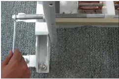
- Assemble lock screw rod to lock position of scissor.
Figure 12. Assemble lock screw rod
- Remove 4 screws of actuator mounting bracket.
Figure 13. 4 screws
- Remove circlips & pin.
Figure 14. Remove circlips & pin
Figure 15. Remove actuator
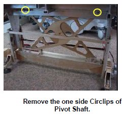
- Remove the circlips of the both Pivot shafts.
Figure 16. Circlips of the both Pivot shafts.
- notice
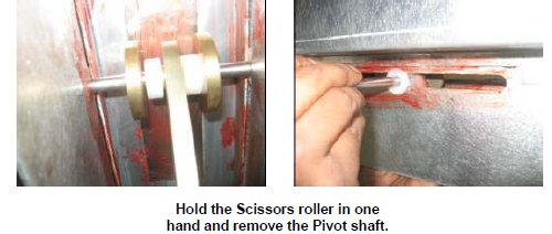
- Remove the Pivot shaft, connecting tabletop and scissors. Hold
the Rollers placed on both the sides thicker scissor in one hand while
removing the Pivot shaft.
Figure 17. Pivot shaft
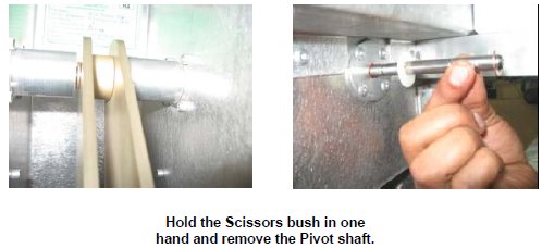
- Hold the scissor bush placed in between scissors in one hand
and remove the Pivot shaft.
Figure 18. Remove the Pivot shaft
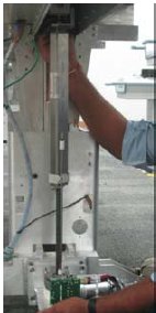
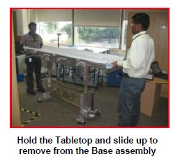
- Now the Table top is free in the Table. Lift the Table Top from
the Base assembly.
Figure 19. Lift the Table Top
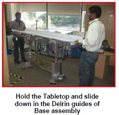
- Now slide down the New Table top on the Delrin guides of the
Front and Rear Plate.
Figure 20. New Table top
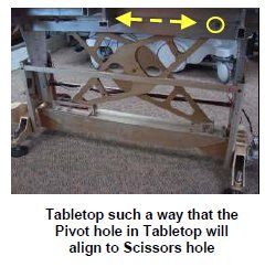
- Move the Table top on either side and adjust such a way that
the Pivot shaft Hole of Table top will align with the scissor hole.
Figure 21. Move the Table top
- notice
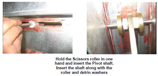
- Insert the Pivot shaft, connecting tabletop and scissors. Hold
the Rollers placed on both the sides thicker scissor in one hand while
inserting the Pivot shaft.
Figure 22. Insert the Pivot shaft
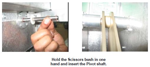
- Hold the scissor bush placed in between scissors in one hand
and insert the Pivot shaft.
Figure 23. Insert the Pivot shaft.
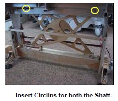
- Insert the circlips of the both Pivot shafts.
Figure 24. insert the circlips
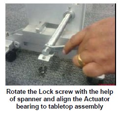
- Rotate the Lock screw with the help of spanner (14mm) and align
the Actuator bearing to tabletop assembly.
Figure 25. Align the Actuator bearing
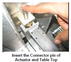
- Insert the connecting shaft to the Tabletop connecting the actuator
assembly.
Figure 26. Insert the connecting shaft
- Assemble pin & circlip for new actuator. In this case, actuator
mounting bracket holes will not be aligned with tapped hole in lower
base of table.
Figure 27. Assemble pin & circlip for new actuator
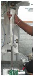
Figure 28. Placing Actuator
- notice
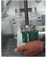
- Rotate lock screw rod to move tabletop down and align screw
mounting holes.
Figure 29. Rotate lock screw rod to move tabletop down
- Assemble actuator mounting screws and tighten.
Figure 30. Assemble actuator mounting screws
- Remove lock screw rod.
Figure 31. Remove the Lock screw
- Fix the Up LS Actuator to the table top. And then the Lock nut
to the Up LS actuator.
Figure 32. Up LS Actuator
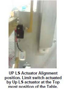
- Ensure the orientation of the Up Ls actuator such a way that
it actuates the limit switch when the table is taken to top most condition.
Figure 33. Up LS actuator
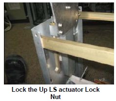
- Tighten the Lock nut of the Up LS Actuator.
Figure 34. Lock nut
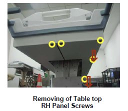
- Remove the screws marked of the RH Table Top Panel and pull
down the panel.
Figure 35. RH Table Top Panel
- Rout the Home sensor cable in the table top.
Figure 36. Rout the Home sensor cable
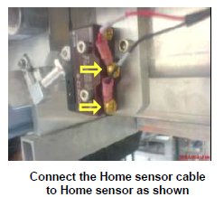
- Connect the Home sensor cable to the Home sensor.
Figure 37. Connect the Home sensor cable
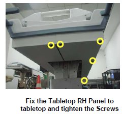
- Fix the RH Table top panel back to the table and tighten the
screws.
Figure 38. Fix the RH Table top panel
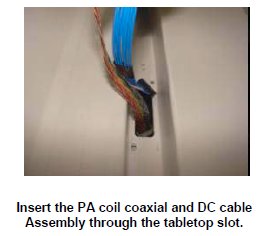
- Insert the PA coil coaxial and DC cable Assembly from the top
of the Tabletop.
Figure 39.
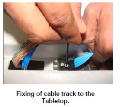
- Fix the Cable track of the PA coil coaxial and DC cable Assembly
to the Tabletop.
Figure 40. Fix the Cable track
- Fix the support block to the Table top.
Figure 41. support block
- Rout the cables in the table and wind the spiral tube around
all Assemblies.
Figure 42. Rout the cables in the table
- Assemble the cradle to the table.
- Connect the cables of the table.
- Level the table.
- Dock centering and Height adjustments.
- Fix the scissor covers from the table.
- Fix the FRP Covers of the Table.
 |
|
|
1 Finalization
Procedure
- Turn the system power on. Refer to Lockout / Tagout for System Cabinet PDU Main Breaker.
- Level the table and adjust the height. refer to LEVELING FIXED TABLE and TOP HEIGHT ADJUSTMENT.
- Check the Fixed Table. Refer to TABLE CHECKS AFTER INSTALLATION.
- Perform Express Coil MCQA Test to check that the PA coil cable is properly connected.