Lockout / Tagout for System Cabinet PDU Main Breaker
Prerequisites
This document covers System Cabinet PDU Main Breaker - Lockout and System Cabinet PDU - Restoring Power. Prior to performing work on the System Cabinet electronics (except PDU) and electronics in Magnet Room, the steps in this Lock Out Tag Out Procedure must be performed by a LOTO Authorized GE Field Engineer. Completing all steps in this procedure will ensure a safe environment when working on these parts.
1 Power Down the computer subsystems
Procedure
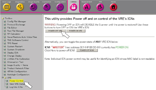
- From Common Service Desktop, click 'Utility / VRE / Power Control'
and select [POWER OFF VRE] to turn off the VRE.
Figure 1. VRE Soft Power OFF
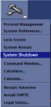
- To shut down the system, click the arrow on the Tools
High Level Access tab, select System Shutdown, and then click [Yes] to confirm the shut down.
Figure 2. System Shutdown
- Confirm that the system is shut down.
2 System Cabinet PDU Main Breaker - Lockout
Procedure
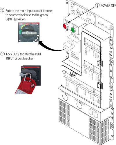
- At the front panel of the PDU, press the Power Off button.
- Rotate the larger main breaker labeled INPUT counter-clockwise to the green, OFF (O) position.
- Lock Out Tag Out the PDU “INPUT” circuit breaker.
- Press on the left-pointing arrow on the end of the handle to expose the location where the lock and tag can be placed.
- Lock and tag out the PDU “INPUT” circuit breaker.
Figure 3. MAIN INPUT BREAKER IN THE OFF POSITION
3 System Cabinet PDU - Restoring Power
Procedure
- Alert necessary personnel that power is being re-applied.
- Remove the Lock and the Tag from the PDU “INPUT” circuit breaker.
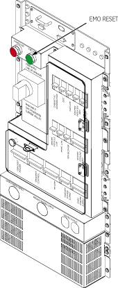
- Rotate the larger main breaker labeled INPUT clockwise to the Red, 1 ONposition.
- Press the EMO RESET switch.
Figure 4. EMO RESET switch
- Boot Signa and log into scanning level.
4 Finalization
Procedure
- Insure all subsystems have powered up successfully
- Do a test phantom scan to insure proper scanning