TABLE CONTROL BOARD CABLES
Prerequisites
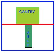
Figure 1. DO NOT TAKE THE TABLE BEYOND THE MARKED LINE
Procedure
- System Power must be turned OFF. Refer to Lockout / Tagout for System Cabinet PDU Main Breaker...;
- Disconnect the Table from MR Magnet; take it out from the Magnet
room. Refer to TAKE TABLE OUT FROM THE MAGNET ROOM
- Remove the scissor covers from the table. SCISSOR COVERS
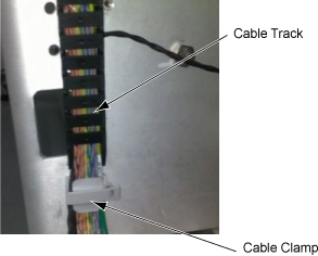
- Remove the cable cramp and track and remove cables.
Figure 2. Cable cramp and track
-
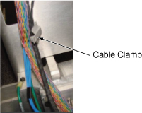
Snap open cable clamp.
Figure 3. Snap open cable clamp
-
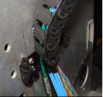
Snap open cable track at end link.
Figure 4. Snap open cable track at end link
-
Snap open cable track.
Figure 5. Snap open cable track
-
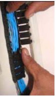
- Remove the cables connected to the Up sensor Limit switch.
Figure 6. Remove the cables
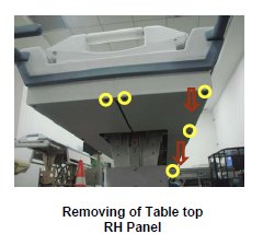
- Remove the Tabletop RH panel in the tabletop assembly.
Figure 7. Remove the Tabletop RH panel
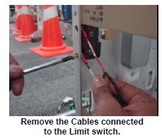
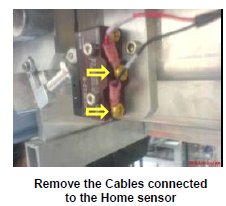
- Remove the cables connected to the Limit switch of the home
sensor.
Figure 8. Remove the cables
- Now the Control board cable assembly is free to remove from table.
- Now take the new Control Cable assembly.
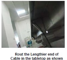
- Rout the lengthier end of the cable in the tabletop.
Figure 9. Rout
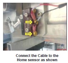
- Connect the cable lengthier end to the Limit switch of the home
sensor.
Figure 10. Connect the cable
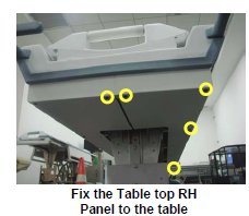
- Fix the Tabletop RH panel in the tabletop assembly.
Figure 11. Fix the Tabletop RH panel
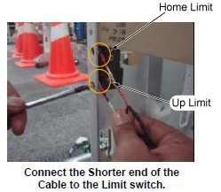
- Connect the Shorter length end of the cable to the Limit switch.
Figure 12. Connect the Shorter length end of the cable
- Rout the cables in the table by reverse order of removal.
- Fix the scissor covers to the table. Refer to SCISSOR COVERS.
- Move the Fixed Table and install to Dock Frame.
- Connect the Cables to the MR Gantry.
1 Finalization
Procedure
- Turn the system Power ON. Refer to Lockout / Tagout for System Cabinet PDU Main Breaker.
- Level the Table and perform Height Adjustment. Refer to LEVELING FIXED TABLE and TOP HEIGHT ADJUSTMENT.
- Fix the FRP Covers of the Table.
- Perform Fixed Table Functional Check. Refer to TABLE CHECKS AFTER INSTALLATION .
- Perform Express Coil MCQA Test to check that the PA coil cable is properly connected.