Bridge Plate Replacement
Prerequisites
Procedure
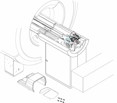
- Remove LPCA Cover. Refer to LPCA Cover Removal.
Figure 1. Removed LPCA Cover
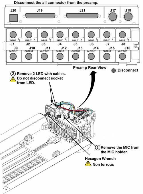
- Remove 2 LED cables from port assy with non-ferrous hexagon
wrench.note:
Do not disconnect the socket from LED.
- Remove the MIC from the MIC bracket.
Figure 2. LED's and MIC Removal
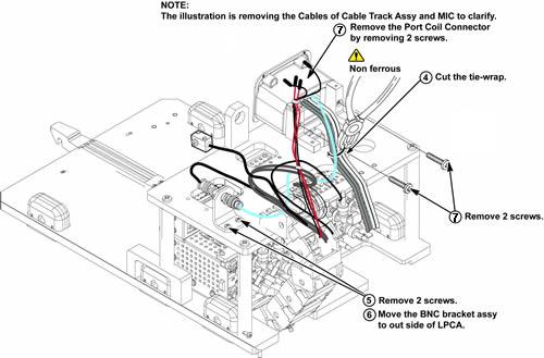
- Cut 4 tie wraps with non-ferrous nipper.
- Remove 2 screws fixing BNC bracket to bridge plate.
- Move the BNC bracket assy to out side of LPCA.
- Remove 2 screws fixing port and hypertron bracket.
Figure 3. Tie-wraps, BNC Bracket and Port Removal
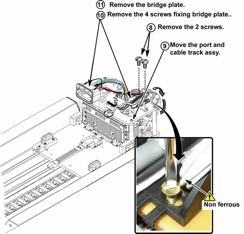
- Remove 2 screws fixing cable and track assy to bridge plate. These 2 screws will be reused to new bridge plate installation.
- Move the cable and track assy and port to out side of LPCA.
- Remove 4 screws fixing bridge plate to LPCA assy. These 4 screws will be reused to new bridge plate installation.
- Remove the bridge plate from LPCA assy.
Figure 4. Bridge Plate Removal
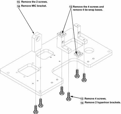
- Remove 4 screws and remove 2 tie-wrap bases.
- Remove 4 screws fixing hypertron brackets.
- Remove hypertron brackets from bridge plate.
- Remove 2 screws fixing MIC bracket.
- Remove MIC bracket from bridge plate.
Figure 5. Removing Parts on Bridge Plate
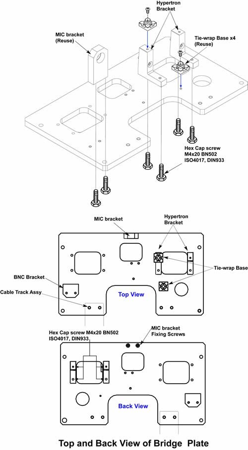
- Install the new hypertron bracket to new bridge plate with new 4 hex cap screws.
- Install removed MIC bracket with 2 screws and 2 tie-wrap bases
with 4 screws to new bridge plate.
Figure 6. Assembling New Bridge Plate
- Install bridge plate to LPCA assy with 4 screws.
- Install all removed parts on the bridge plate by reverse order
of removal.note:
Make sure that all the tie wraps must be fixed at the same position before removal.
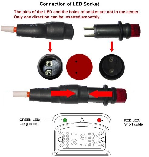
note:If LED cable is removed, relatively longer cable is for green LED and relatively shorter cable is for red LED.
note:Connect the LED cable so that the cable is centered to the LED itself.
Figure 7. Bridge Plate Installation
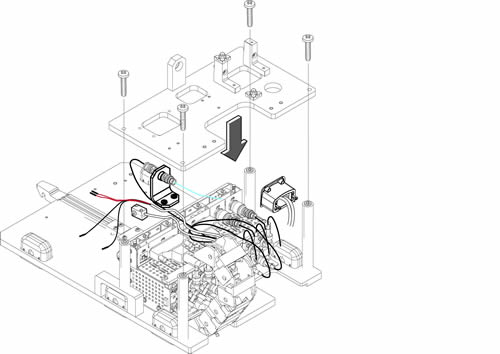
Figure 8. Port and LED
1 Finalization
Procedure
- Restore the Power. Refer to Lockout / Tagout for System Cabinet PDU Main Breaker.
- Run MCR tool.
- Run one head or body scan.