1.5T HD 4CH Coil Troubleshooting
1 Overview
The following tips can be used to troubleshoot common problems with the 4 CH CTL Coil (GE/USAI P/N: 2415369).
2 Tools and Test Equipment
Digital Voltmeter
3 Required Conditions
The following coil configuration names must be installed to run this tool:
-
Coil: HD 4CH CTL Array by GE
-
Config: USCS 12, USTS 34, USLS 56
4 Procedure
4.1 Receiving No Signal
Problem:
You are unable to pre-scan or are scanning and yet receiving no signal.
Possible Solutions:
-
Verify that you have selected the appropriate system coil selection. Refer to the Operators Manual for additional information.
-
Verify the green light above Port A is illuminated. This indicates the coil is properly plugged into the system.
-
Verify that the landmark is correct and that the cradle has not unlatched.
-
Verify that the scan locations and any FOV offsets are correct.
-
Perform a Continuity Check on the external cable using the instructions detailed in section 4.4 (to be performed by a GE authorized Service Engineer only).
-
Verify that the coil is positioned with the cable exiting towards the bore and that the system and coil polarity match.
The polarity of the MR system may be reversed. In such instances, the polarity of the coil will need to be reversed. To easily check the polarity, reverse the orientation of the coil. Run the SNR protocol. If the SNR value is within 5% of the target, the coil’s polarity needs to be reversed. This change can be made in the field by a GE authorized Service Engineer. If the SNR value is less than 95% of the target value, there may be a problem with the coil. Contact GE for further assistance. If you still cannot get a signal, try to scan (transmit and receive) with the body coil. For this test, be sure to remove the imaging coil from the magnet bore before you scan with the body coil. If you still receive no signal the problem probably lies with your MR system. If the scan completes successfully, there is probably a problem with the coil. Contact GE for further assistance. If you are unable to scan with the substitute coil, there may be a system problem related to this particular coil type.
4.2 Image Quality
Problem:
Image quality is not as good as you expect from the Coil.
Possible Solution:
-
Review the selected protocol. If you are performing the Periodic Quality Assurance, be sure your protocol is identical to the protocol provided in your Systems Recommended Protocols. If you are performing diagnostic images, you may need to increase NEX or FOV.
-
Perform a Continuity Check on the external cable using the instructions detailed in section 4.1 below (to be performed by a GE authorized Service Engineer only).
-
Verify that there are no loops in the cables.
-
Verify that there are no metal or ferromagnetic objects close to the coil, patient or magnet (i.e., safety pin, hair pin).
-
Verify that the coil is properly positioned.
-
Verify that your center frequency is within the frequency adjustment range for your system.
-
Verify that the R1, R2 and TG values from the pre-scan are within normally expected ranges.
Perform a system Quality Assurance phantom test. If the values you obtain do not fall within normal operating parameters, investigate this further by performing a phantom scan with the body coil. For this test, be sure to remove the imaging coil from the magnet bore before you scan with the body coil. If you still have the same problems, there is probably an MR system problem. If the body coil scan is satisfactory, acquire a scan both another coil of the exact same type (receive-only, phased array) and the same system coil selection. If the image quality is visibly improved, there may be a problem with the 4CH CTL coil. Contact GE for further assistance. If the image quality still suffers, there may be a system problem related to imaging with this type of coil.
4.3 Artifacts
Problem:
There is a black line or signal void on the image.
Possible Solution:
Verify that there is no metal present in the area being scanned in or on the patient.
Problem:
Some or all of the images appear shaded or exhibit uneven signal or banding.
Possible Solution:
Confirm that no metallic objects are located nearby, outside the FOV. This is especially important on images utilizing Fat Saturation.
If Fat Saturation is being used, verify that the CFA fine adjustment has been optimized.
4.4 External Cable Wear
Problem:
The system will not recognize the coil or scan with the coil attached.
Possible Solution1 - Visual Inspection:
Check the physical condition of following pins on the Hypertronics handle. Refer illustration 1-2 to locate the pins on the Hypertronics Handle.
A1-A2; C1-C4; D1-D2; J1-J6; J9-J10; K9-K10; M5; M7-M10;
Figure 1. Hypertronics Connector
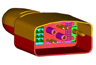
Figure 2. pins on the Hypertronics
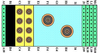
Replace the Cable assembly as per the HD 4CH CTL Cable Replacementprocedure if any of the above-mentioned pins are damaged.
If all the pins are ok, perform the DC Continuity check for the coil as per below procedure.
Possible Solution2 - DC Continuity Test:
-
Remove the cable as per procedure given in Section 4 (Step 1-4) of HD 4CH CTL Cable Replacement procedure. Check the DC continuity between Coil Side Connectors (SMBs) and the Hypertronics coax connectors using Digital Voltmeter in resistance mode. Perform the continuity check between the Hypertronics pin also as given in the table 1. Replace the cable, if it fails to pass the continuity test specs as per Table 1.
-
Check if any of the pins from J1 to J6 of Hypertronics handles is shorted to the ground. The outside conductor of a coaxial connector in column C or D can be used as ground. If any of the pins is shorted to ground, replace the cable as per HD 4CH CTL Cable Replacementprocedure.
-
Check for the ground pin continuity check between M5, M8 and the RF ground pin for C1.The resistance should be less than 1 Ohm. If it fails the ground pin continuity test, replace the cable as per HD 4CH CTL Cable Replacementprocedure
-
Perform the SNR Test after the installation on the new cable.