Dock Centering and Dock Hardware Adjustments
Prerequisites
Overview
The Dock Hardware Adjustment procedures describe how to adjust the Motor On Switch Actuation and multiple Gear Assembly Adjustments for noise reduction. Each of these procedures requires removal of the dock as the initial step:
-
Motor On Switch Actuation Adjustment - The Motor On actuation switch in the dock assembly should be adjusted so it is activated when the Table Up foot pedal is pressed approximately 3/4 of its total length of travel. This is factory adjusted; however, it is possible to adjust the position of the Motor On switch in the field to maintain the proper actuation level.
-
Gear Assembly Noise Adjustments - The dock motor gear box has a clutch that prevents backlash on the gears in the gear box. This clutch is not intended to regulate dock motor speed. This clutch simply prevents gear backlash, which would make the gear assembly noisy. Perform procedures in Cam Adjustment Procedure, Motor Tube Spring Check, and Clutch Adjustment in the sequence presented, to correct excessive gear assembly noise. There are three probable causes of a noisy gear assembly:
-
Cam improperly adjusted
-
Excessive play on motor tube spring
-
Clutch improperly adjusted
-
The Dock Centering procedure provides the Longitudinal Adjustment (in and out), and the Lateral Adjustment (left to right) to center the dock. For proper Patient Transport docking, the dock assembly must be adjusted to meet two criteria:
-
Gap between patient transport top and front of Magnet Enclosure must be 3/4 ± 1/4 inch (19.0 ± 6.4 mm). This is to ensure that the gap is narrow enough so UP Limit Sensor operates properly, and wide enough so there is no finger pinch hazard when docking transport.
-
Dock assembly must be square to the bridge, so axis of cradle travel is the same for both patient transport and bridge.
1 Removal of Dock
Procedure
 danger
- Follow instructions in LCC Dock Replacement to remove the dock from the magnet room.
- Continue to selected procedure:
-
Dock Adjustment:
-
Motor On Switch Actuation Adjustment Motor On Switch Actuation Adjustment Procedure
-
Cam Adjustment Cam Adjustment Procedure
-
Motor Tube Spring Check Motor Tube Spring Check
-
Clutch Adjustment Clutch Adjustment
-
-
Dock Centering:
-
Longitudinal Adjustment (In and Out) Longitudinal Adjustment (In and Out)
-
Lateral Adjustment (Left to Right) Lateral Adjustment (Left to Right)
-
-
2 Motor On Switch Actuation Adjustment Procedure
Procedure
- Follow instructions in LCC Dock Replacement to remove the dock from the magnet room.
- Remove four mounting bolts from main dock cover (Figure 1).
Figure 1. Dock Cover Removal
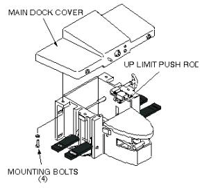
- Slide main dock cover forward until Up Limit switch push rod just clears main dock cover holes (Figure 1).
- Remove front cover by removing two nuts securing front cover
to dock (Figure 2).
Figure 2. Motor On Switch Adjustment
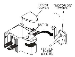
- Loosen two mounting screws securing Motor On switch to side of dock assembly (Figure 2).
- Adjust Motor On switch position so it is activated (clicks) when the Table Up foot pedal is pressed approximately 3/4 of its total length of travel.
- After adjustment is complete, tighten two mounting screws.
- Reinstall front cover by attaching two mounting nuts.
- Carefully position main dock cover so that Up Limit switch push rod is aligned with upper hole in main dock cover.
- Replace main dock cover by securing four mounting bolts (Figure 2).
- warning
- Follow instructions in LCC Dock Replacement to install the dock assembly.
- If continuing on to Cam Adjustment Procedure proceed to Cam Adjustment Procedure. Otherwise continue to Finalization.
 |
3 Cam Adjustment Procedure
Procedure
- Follow instructions in LCC Dock Replacement to remove dock from the magnet room.
- Remove four mounting bolts from main dock cover (Figure 3)
Figure 3. Dock Cover Removal
- Slide main dock cover forward until Up Limit switch push rod just clears dock cover holes (Figure 3).
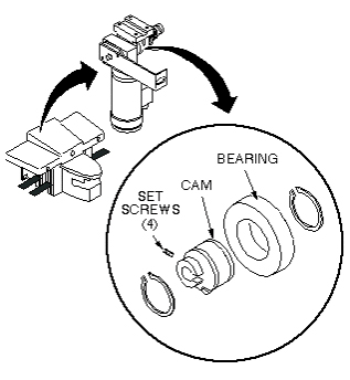
- Check four set screws on motor cam (Figure 4). If set screws are loose, apply Loctite
242 and Primer T to set screws and tighten. Allow fifteen
minutes to harden.
Figure 4. DOCK MOTOR CAM ADJUSTMENT
- Carefully position main dock cover so that Up Limit switch push rod is aligned with upper hole in dock cover (Figure 3).
- Replace main dock cover and secure with four mounting bolts.
- warning
- Follow instructions in LCC Dock Replacement to install the dock assembly.
- Exercise Table Up pedal to see if gear noise has been eliminated. If not, remove dock assembly as detailed in Removal of Dock, and perform Motor Tube Spring Check
4 Motor Tube Spring Check
Procedure
- warning
- Follow instructions in LCC Dock Replacement to remove dock from the magnet room.
- Remove four mounting bolts from main dock cover, as shown below.
Figure 5. Dock Cover Removal
- Check play between tube spring and motor mounting bracket (Figure 6).
Figure 6. Motor Tube Spring
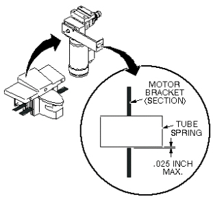
- If play is more than 0.025 inch (0.6 mm), replace tube spring.
- Replace main dock cover on dock assembly
- warning
- Follow instructions in LCC Dock Replacement to install the dock assembly.
- Exercise Table Up pedal to see if gear noise has been eliminated. If not, remove dock assembly as detailed in Removal of Dock Procedure, Removal of Dock and perform Clutch Adjustment, Clutch Adjustment.
5 Clutch Adjustment
Procedure
- warning
- If the dock is not already removed from the magnet room, follow instructions in LCC Dock Replacement to remove dock from the magnet room.
- Remove four mounting bolts from main dock cover, as shown below.
Figure 7. Dock Cover Removal
- Loosen set screw on clutch adjustment knob (Figure 8).
Figure 8. Dock Motor Clutch Adjustment
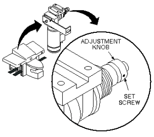
- Adjust knob two clicks tighter (clockwise), and tighten set
screw.note:
Do not adjust clutch more than two clicks at a time. The clutch should not be tightened to the point where it affects the dock motor function.
- Replace main dock cover on dock assembly.
- warning
- Follow instructions in LCC Dock Replacement to install the dock assembly.
- Exercise the Table Up pedal to see if gear noise has been eliminated. If not, remove dock assembly as detailed above Removal of Dockand repeat adjustment procedures as detailed in Cam Adjustment Procedure Cam Adjustment Procedure through Clutch Adjustment Clutch Adjustment.
6 Longitudinal Adjustment (In and Out)
Procedure
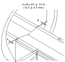
- With the patient transport docked, measure the distance from
the patient transport top to the front end bell, as shown below. Dimensions
A and B should be 3/4 ±1/4 inch (19.0 ±6.4 mm) and equal
to each other so the patient transport top is colinear with the bridge.
Figure 9. Table Docking Measurement for Dock
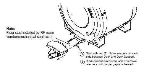
- Follow instructions in LCC Dock Replacement to remove dock from the magnet room.
- If adjustment is required, add or remove washers until the proper
gap is achieved, as shown below.
Figure 10. Dock Positioning Adjustment
- warning
- Follow instructions in to install the dock assembly.
7 Lateral Adjustment (Left to Right)
Procedure
- Raise table to maximum height using the UP foot pedal.
- Dock the Patient Transport.
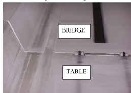
- Check the alignment of the Patient Transport against the bridge.
The guide rail down the length of Patient Transport top should match
the guide rail down the length of bridge, as shown below. For left-to-right only: Height is adjusted using the Table Top Height Adjustment procedure.
Figure 11. Aligning Guide Rails
- If adjustment is required:
-
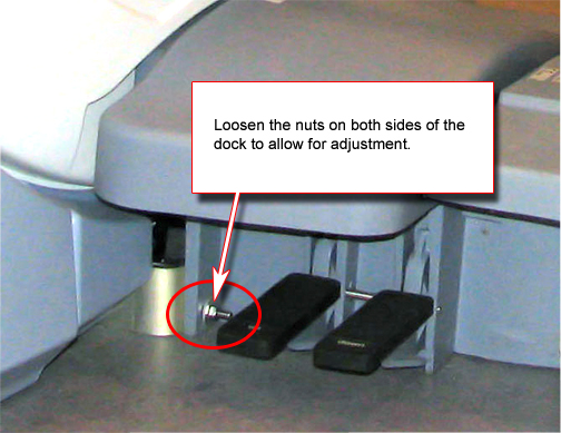
Loosen the screws mounting the dock bracket to the magnet and the cover support brackets to dock bracket, and loosen the nuts mounting the dock to the dock bracket. See Figure 12.
- warning
- Move dock to proper position so guide rails line up. Lift the dock bracket slightly off the ground (approximately 1 mm) and tighten all fasteners.
Figure 12. Dock Positioning Adjustment

-
8 Finalization
Finalization
No finalization steps.