1.5T HD Knee Array Coil Setup and SNR Test
Prerequisites
1 Legacy Phantom Setup
Procedure
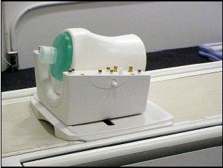
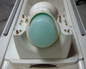
- Place the 1.5T HD Knee Array, the phantom positioner, and the
phantom on the patient cradle as shown in Figure 1. Note the serial number of the coil.
Figure 1. Coil and Phantom Setup
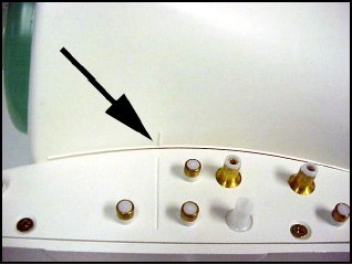
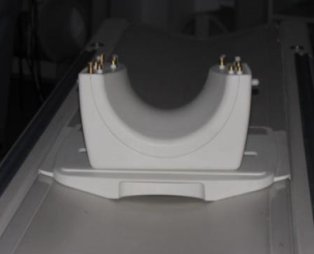
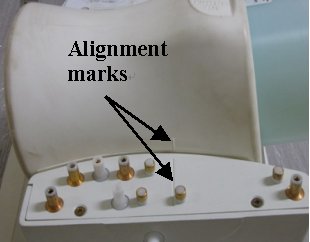
- Position the coil in the cradle, connect the cable as shown
in Figure 2
Figure 2. Phantom Positioner Alignment Marks
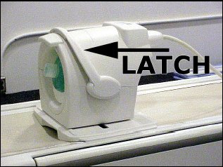
- Being careful to align the connector pins, place the anterior
coil section onto the posterior coil section and latch into place.
(Figure 3 ) The scanner will not operate if the coil sections
are not latched correctly .
Figure 3. Anterior Coil Section in Place
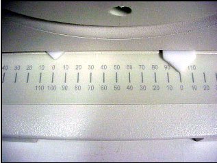
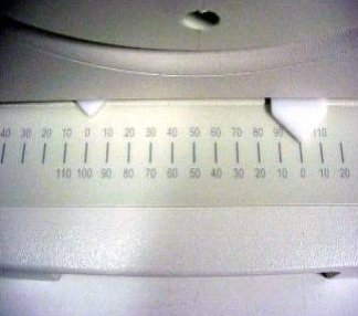
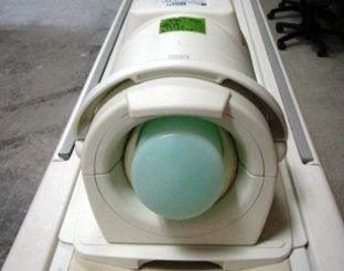
- Ensure that the coil is aligned and centered with respect to
the baseplate as indicated by the arrows on the baseplate offset scale.
(Figure 4 )
Figure 4. Align and Center the Coil
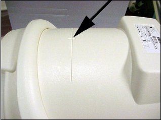
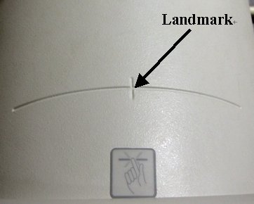
- Establish an axial landmark using the reference mark on top
of the coil. (Figure 5 ) Advance to scan.
Figure 5. Establish Landmark
- Perform the Multi-Coil Quality Assurance Tool.
2 Unified Phantom Setup
Procedure
- Place the lower section of the coil on the patient table as
shown in Figure 6.
Figure 6. Place the lower section
- Align the alignment mark on the coil to Zero position on the
scale as shown in Figure 7.
Figure 7. Align the alignment mark
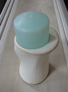
- Place the large cylindrical unified phantom into the Positioner
as shown in Figure 8.
Figure 8. Place the large cylindrical unified phantom
- Place this Phantom-positioner setup on the lower part of the
coil as shown in Figure 9.
Figure 9. Place this Phantom-positioner
- Ensure that the phantom positioner is aligned with the posterior
coil section as indicated by the marks on the positioner and the coil
(Figure 10)
Figure 10. phantom positioner aligned
- Carefully align the connector pins on the lower part of the
Coil with the upper part of the coil and latch both the coil sections
into place as in Figure 11. (The scanner will not operate
if the coil sections are not latched correctly).
Figure 11. align the connector pins
- Connect the coil to respective port of the system LPCA and Landmark
the coil at the cross mark available near the handle of the coil (Figure 12) and advance to scan.
Figure 12. Land mark
- Perform the Multi-Coil Quality Assurance Tool.
3 Finalization
Finalization
No finalization steps.