1.5T GP Flex Coil SNR Test
Prerequisites
Follow this process to prepare for the SNR test using the Signa Horizon 1.5T /Signa Horizon LX 1.5T /Signa Twin Speed 1.5T/Signa Infinity 1.5T Signa Infinity Twin Speed 1.5T/Signa CV/i 1.5T/Signa MR/i 1.5T /Signa HDe 1.5T GP Flex coil.
-
GE catalog Part number :M1085GF
1 Scanner Verification
Perform system level Signal to Noise Check. Refer to Service Methods CD; System Level Procedures; Functional Checks; Signal to Noise Check.
2 Coil Imaging Performance Verification
2.1 Explanation of Procedure
SNR measurements for the GPFLEX coil require sets of signal and noise scans. Refer to the Data Sheet in Appendix 5-1 to understand the data required to calculate the SNR. All ROI measurements are made on the individual element images, not on the composite image. The image quality check uses two different protocols for signal and noise image acquisition. The signal scan is an FSE sequence used to minimize susceptibility and B0 inhomogeneity effects. The noise scan is a GRE sequence that has a Control Variable (do_noise) to eliminate the transmit RF completely during the scan. The signal scan must be run prior to the noise scan as the R1, R2, and TG values from the signal scan are used for the noise scan.
Procedure
2.2 Signal Scan
The following procedure is specific to the LX platform but can be easily adapted for 5.x systems.
Procedure
- The Quad Head Coil must be completely removed from the cradle before performing any body or surface coil scans. Failure to do this may result in damage to the Quad Head Coil T/R network.
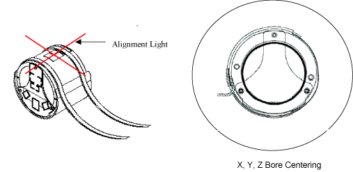
- At the magnet, press “Alignment Light” button to turn on
the light. Move the cradle to align the coil to the alignment lights as shown
in Figure 1. Press “Landmark”
button to landmark the alignment.
Figure 1. Phantom Setting
- Move the coil to scan position by pushing the “Move to Scan” button, ensuring cable does not get snagged.
- At the console, set the protocols as mentioned in Table 4.
- Click [Save Series] to download the protocols, then click [Prepare to Scan].
- Run [Auto Prescan]. Record the R1, R2 and TG values on the SNR Data Sheet (found at the end of this manual).
- Run [Scan]
2.3 Noise Scan
A signal scan must be run prior to the noise scan as the same R1, R2 and TG values must be used for both the signal and noise scans. Do not run an Auto Prescan prior to the noise scan as the values will be changed.
Procedure
- Copy the signal scan series. Use [Copy Series] (highlight signal series and click right mouse button) and [Paste Series] in RX Manager.
- Click [View Edit] and set the protocols as mentioned in Table 5.
- Click [Save Series] and click [Prepare to Scan].
- Open [Display CVs] menu under [Research Operations]. Set the “rhformat” and “do_noise” CVs to “1”.
- Run [Manual Prescan], do not make any changes, and click [Done].
- Run [Scan].
2.4
Procedure
3 SNR Image Analysis
Procedure
- Perform SNR Measurement.
Regions of interest in both signal and noise images can be measured directly in the image browser. Click the user interface button Measure, select the circular or rectangular shape, and adjust its size and orientation when the shape is displayed in the selected image. Mean, standard deviation, and area of the ROI will appear in the lower right corner of the image.
Figure 2.
 note:
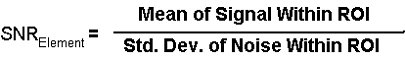
note:The SNR calculation uses the MEAN of the signal image and STANDARD DEVIATION of the noise image. SNR is measured for each element, not on the composite image.
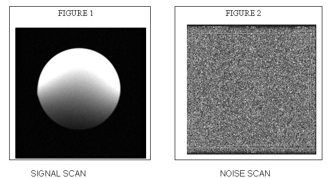
For the signal measurement, choose an ROI covering approximately 80% of the phantom. Also measure the noise with an ROI covering 80% of the FOV. Examples of typical ROIs are shown in Figure 3.
Figure 3. Signal and Noise Image
- Check that the result satisfies the specification.
The SNR measurements must be greater than or equal to the following specifications:
note:Image 1 and image 5 are collected to verify that the phantom is correctly centered. For example, you would want images 1 and 5 to be the same size. If they are not the same size, then the phantom should be repositioned relative to the coil center.
4 SNR Data Sheet
Procedure
- Enter in Data Sheet.
5 Coil Configuration
Procedure
- The following table is coil configuration.
6 Finalization
Finalization
No finalization steps.