RF Amplifier Diagnostics
1 Diagnostic Link
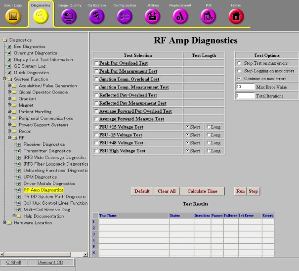
Diagnostics >> System Function >> RF >>RF Amplifier Diagnostics
Diagnostics >> Hardware Location >> System Cabinet >> RF >>RF Amplifier Diagnostics
Figure 1. RF Amplifier Diagnostics
2 Purpose
 |
|
This document describes the theory of each test in RF Amplifier Diagnostics.
3 Peak Pwr Overload Test
This diagnostic provides self-test functions of internal amplifier circuitry. This self-test is performed on an overload detection function of Peak Forward Power Overload Circuit. The test signal that is input from the amplifier to control board is replaced by a test voltage that is generated by circuitry on the control board under software control. For Overload Circuit Test, the trip point for detecting the overload is temporary adjusted below the level of the inject test input voltage in order to verify the functionality of the circuit.
4 Peak Pwr Measurement Test
This diagnostic provides self-test functions of internal amplifier circuitry. This self-test is performed on a measurement function of Peak Forward Power Measurement Circuit. The test signal that is input from the amplifier to control board is replaced by a test voltage that is generated by circuitry on the control board under software control. For Measurement Circuit Test, the diagnostic will inject a test voltage into the measurement circuit, cause an analog to digital conversion to occur, and read and compare the conversion results to an expected value.
5 Junction Temp. Overload Test
This diagnostic provides self-test functions of internal amplifier circuitry. This self-test is performed on an overload detection function of Junction Temperature Overload Circuit. The test signal that is input from the amplifier to control board is replaced by a test voltage that is generated by circuitry on the control board under software control. For Overload Circuit Test, the trip point for detecting the overload is temporary adjusted below the level of the inject test input voltage in order to verify the functionality of the circuit.
6 Junction Temp. Measurement Test
This diagnostic provides self-test functions of internal amplifier circuitry. This self-test is performed on a measurement function of Junction Temperature Measurement Circuit. The test signal that is input from the amplifier to control board is replaced by a test voltage that is generated by circuitry on the control board under software control. For Measurement Circuit Test, the diagnostic will inject a test voltage into the measurement circuit, cause an analog to digital conversion to occur, and read and compare the conversion results to an expected value.
7 Reflected Pwr Overload Test
This diagnostic provides self-test functions of internal amplifier circuitry. This self-test is performed on an overload detection function of Peak Reflected Power Overload Circuit. The test signal that is input from the amplifier to control board is replaced by a test voltage that is generated by circuitry on the control board under software control. For Overload Circuit Test, the trip point for detecting the overload is temporary adjusted below the level of the inject test input voltage in order to verify the functionality of the circuit.
8 Reflected Pwr Measurement Test
This diagnostic provides self-test functions of internal amplifier circuitry. This self-test is performed on a measurement function of Peak Reflected Power Measurement Circuit. The test signal that is input from the amplifier to control board is replaced by a test voltage that is generated by circuitry on the control board under software control. For Overload Circuit Test, the trip point for detecting the overload is temporary adjusted below the level of the inject test input voltage in order to verify the functionality of the circuit.
9 Average Forward Pwr Measurement Test
This diagnostic provides self-test functions of internal amplifier circuitry. This self-test is performed on a measurement function of Average Forward Power Measurement Circuit. The test signal that is input from the amplifier to control board is replaced by a test voltage that is generated by circuitry on the control board under software control. For Measurement Circuit Test, the diagnostic will inject a test voltage into the measurement circuit, cause an analog to digital conversion to occur, and read and compare the conversion results to an expected value.
10 Average Ref Pwr Measurement Test
This diagnostic provides self-test functions of internal amplifier circuitry. This self-test is performed on a measurement function of Average Reflected Power Measurement Circuit. The test signal that is input from the amplifier to control board is replaced by a test voltage that is generated by circuitry on the control board under software control. For Measurement Circuit Test, the diagnostic will inject a test voltage into the measurement circuit, cause an analog to digital conversion to occur, and read and compare the conversion results to an expected value.