XFD-PS LEDs
1 OVERVIEW
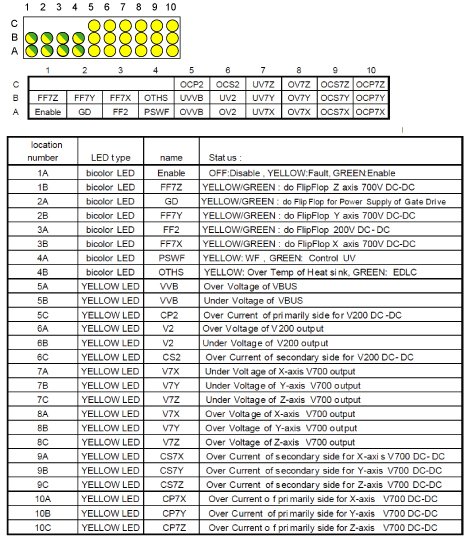
The power supply contains 3 transformers, one for each axis. The primary current is controlled by the power supply and the secondaries of the transformers feed the Gradient Amplifiers. The over current faults are separated into primary side and secondary side faults. The following tables shows the status of each LED.
2 LEDS
-
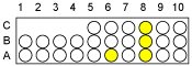
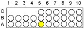
5C, 10A, 10B, 10C: These indicate over currents in the transformer primaries. This is an uncommon fault that would indicate a shorted transformer primary.
-
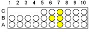
6C, 9A, 9B, 9C: These indicate over currents in the transformer secondaries. The main 2 causes are a blown IGBT in the Gradient Amplifier or a shorted diode module in the power supply. If it is a Gradient Amplifier IGBT, the gate drive indicators located above the heatsink on the Gradient Amplifier will be out.
-
6A, 8A, 8B, 8C: These indicate over voltages on the output of the power supply. Loose connectors to the Gradient Amplifier can cause this problem.
-
6B, 7A, 7B, 7C: These indicate under voltages on the output of the power supply. Shorted semiconductors in the Gradient Amplifier or Power Supply can cause these.
-
5A: This indicates an over voltage on the input bus of the power supply. The 208 VAC of the power supply goes through a 3-phase rectifier to feed this bus. If you see this fault, check the tapping of the PDU and measure the 208 VAC on the terminal block in the back of the power supply.
-
5B: This indicates an undervoltage on the input bus of the power supply. Mis-tapping the PDU or line sags can cause this.
-
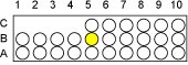
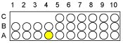
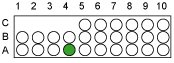
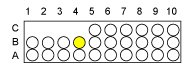
4A Yellow: This indicates internal Wire Fault.
-
4A Green: This indicates one of 2 faults. It could be an undervoltage on the 5V or 15V on the control board.
-
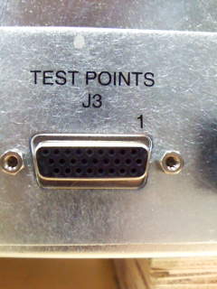
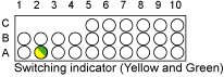
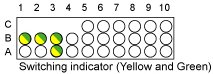
2A: This shows the switching of the Gate Drive power supply. If this light is only ever-solid yellow or only solid green, it means there is a problem on the control board or gate driver and the IGBTs will never switch. Please measure the DC voltage between J3 test point 25 pin (front of the PS control, 25 pin is located on the connector of the bottom line ,2nd from the left) and GND chassis. 7.5 ± 1 ~ 2 volt is normal. If the voltage is 0V or 15 V, try to replace PS control or PS assy.
If the yellow and green light are both solid and the voltage is normal, XFA amp or GP3 may have trouble. Please check them first and solve it.
-
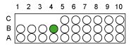
4B Yellow: Heat sink over temperature. Check that the cabinet fan is running in the correct direction. Check that MCS or LCS is working.
-
4B Green: EDLC is sending error signal.
-
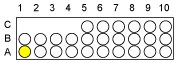
1A Yellow: Lights whenever one of the faults described above is true, or lights while the GP3 is sending reset signal.
-
3A, 1B, 2B, 3B: IGBT switching indicators.
-
1A Green: Lights when the power supply is enabled by the GP.