TRF BLD
1 Diagnostic Link
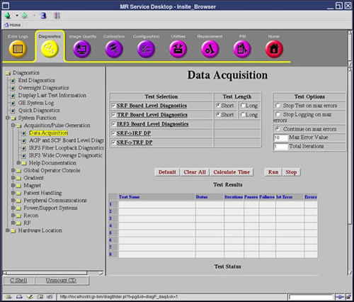
Diagnostics >> System Function >> Acquisition / Pulse Generation >> Data Acquisition
Diagnostics >> Hardware Location >> System Cabinet >> CAM >> Data Acquisition
Figure 1. TRF BLD
2 Purpose
The Trigger and Rotation Functionality (TRF) Board Level Diagnostic (BLD) performs the tests listed below.
3 Components Tested
This board relies heavily on the functionality of the SRF and STIF to perform these tests. Patterns used to validate the memory are selectable and are listed below. The items highlighted in green in the following block diagrams show what has been tested.
4 Requirements
None
5 Block Diagrams
Figure 2. SRF for TRF Block Diagram
Figure 3. TRF Block Diagram
Figure 4. STIF Board Level Diagnostics Block Diagram
6 Test Sequence
Short vs. Long Tests: The short test performs a walking ones and walking zeroes pattern whereas the long test will perform a walking ones, walking zeroes, 0xaaaa, 0x5555, and possibly other patterns. As a result, selecting the long test will generally provide a longer and more exhaustive test. If the problem is highly intermittent then it may be desirable to run a long test.
Click Calculate Time to get an estimate of the time it will take to run the selected diagnostics.
0.TRF serial number verify tests
-
Registers Initial State Verification
-
Registers Write Verification
-
Status Check Tests
-
PCI to DPR Memory Tests
-
DPR Semaphore Tests
-
Semaphore Registers Verification
-
HPI Data Bus Verification
-
HPI Functional Verification
-
HPI to C6X Internal Program Memory Tests
-
HPI to C6X Internal Data Memory Tests
-
HPI to DPR Memory Tests
-
HPI to C6X External SSRAM Memory Tests
-
C6X Self Tests
-
Duart Tests
-
C6X to AGP HPI Interrupt Tests
-
AGP to C6X HPI Interrupt Tests
-
McBSP WARP Serial Loopback Test
-
McBSP SPU Serial Loopback Test
-
McBSP SPU Serial Loopback Test
-
Warp External WMI Loop Test
-
SPU External Loop Test
-
SPU Trigger Internal Test
-
SPU External Loop Test
Memory Pattern
-
0 MINIMUM or Power Up = 0's, F's, and an Address Test (Incrementing values)
-
1 Short = 0's, F's, A's, 5's and an address test.
-
2 Medium = 0's, F's, A's, 5's, walking one's, and an address test.
-
3 Long = 0's, F's, A's, 5's, walking one's, walking 0's, and an address test.
7 Expected Results
Output values are judged pass or fail. In the event of failure, the details of the failure can be found in the GE System Log.
Although, in the case of errors you can click the 1st Error number to see the nature of the error, it is recommended that you view the GE System Log to view all the errors that were recorded.
The Test Options settings should not be changed from their default settings unless instructed to do so by a GE Healthcare engineer. There are very few circumstances when these settings ever need to be changed.
 |
|