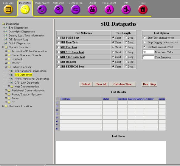
SRI STIF Loop Test
1 Diagnostic Link
Diagnostics >> System Function >> Patient Handling >> SRI Data Paths
Diagnostics >> Hardware Location >> Magnet Room >> SRI Data Paths
Figure 1. SRI Data Paths
2 Purpose
This diagnostic can be used to test the SRI fiber optic communication path coming out of the MGD chassis.
3 Components Tested
The SRI module is not tested by this diagnostic.
4 Requirements
This test requires an external loopback path between the J15 and J16 fiber optic ports on the STIF board (MGD chassis). There are two ways to do this:
-
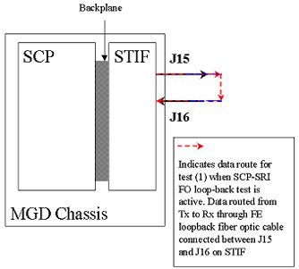
Obtain the fiber optic loopback test cable, part number 46-287282G1. Remove the existing product cables and install the test cable between J15 and J16 on the STIF Board located in the rear of the MGD Chassis. See comments associated with red dotted path in illustration below. Now run the diagnostic. Remove the test cable and reconnect the product cables when testing is finished.
5 Block Diagram
Figure 2. SRI STIF Loopback Block Diagram
6 Test Sequence
This diagnostic uses the SCP board in the MGD chasis to transmit a sequence of data from its SRI Tx port on the STIF board. The loopback cable you provide should return this data to the Rx port on the STIF board.
7 Expected Results
Output values are judged pass or fail. In the event of failure, the details of the failure can be found in the GE System Log.
In the case of errors click the 1st Error number to see the nature of the error.
8 Etcetera
General fiber optic cable tips:
-
Verify that the fiber cables are fully seated in their sockets.
-
Verify that the cable is not kinked or pinched. Sharply bent plastic fibers block the light path.
-
Inspect the ends of the cables and verify that the plastic light conductors are even with the ends of the gray or blue connectors. The fiber cable may be partially pulled out of the connector leaving a gap in the light's path.
The fiber optic loopback adapter is a short length of single conductor fiber optic cable with a male connector on each end. Many SRI modules have this cable stored inside of there case. If it is missing then a new one can be made from the parts provides in the fiber optic connector repair kit (46-30145061)
Click Calculate Time to get an estimate of the time it will take to run the selected diagnostics.
Other than Test Iterations, the Test Options settings should not be changed from their default settings unless instructed to do so by a GE Healthcare engineer. There are very few circumstances when these settings ever need to be changed.