Magnet Enclosure Button Test
1 Diagnostic Link
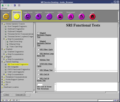
Diagnostics >> System Function >> Patient Handling >> SRI Functional Tests
Diagnostics >> Hardware Location >> Magnet Room >> SRI Functional Tests
Figure 1. SRI Functional Tests Screen
2 Purpose
This test verifies the proper operation of the Operator Control Panel push buttons on the front of the magnet enclosure.
Possible equipment shutdown. Do not press the Emergency Stop buttons on the Display Panel during this test. The Emergency Stop buttons are not disabled during the test, and will shut down all cabinets that provide power to the magnet room.
3 Components Tested
-
Magnet Enclosure Operator Control Pushbuttons Codes
4 Requirements
None
5 Test Sequence
 |
|

-
Select Magnet Enclosure Button Test.
-
Click Run.
-
Press each button and verify the code displayed on the Longitudinal Position (right) display corresponds to the button numbers shown in Illustration 2. Very the Scan Time Remaining (left) display increments as buttons are pressed.
Figure 2. Buttons/Display Codes without In-Room Monitor
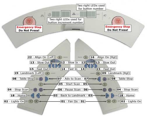
Landmark and Align On button codes are different. The Landmark and Align On buttons on the Left Operator Control are on a different circuit than the corresponding buttons on the Right Operator Control. The Longitudinal Position display shows a different number code, depending on whether the button is on the left or right.
6 Expected Results
When this test is performed, the alternate functions replace those that are normally executed when the buttons are pressed. Instead, each button has a corresponding number assigned to it. A button's corresponding number is displayed on the Longitudinal Position (right) display for when the button is pressed (see Note under Figure 2for exceptions). Also, the Scan Time Remaining (left) display increments as buttons are pressed, providing a means of verifying operation of the switch debounce function. Proper operation of a switch debounce function is indicated by the Scan Time Remaining display increments one count each time the switch is pressed and released. There are two failure modes for the Button Test: an open switch, and a shorted switch. An open switch displays no code when pressed; a shorted switch causes the incorrect code to be displayed. In the case of a shorted switch, the incorrect code displayed indicates which switch is shorted. For example, if Start Scan is pressed, and the code displayed is 02, the Lights On switch is shorted.