Keyboard STIF Loop Test
1 Diagnostic Link
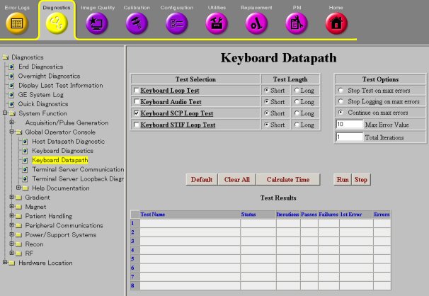
Diagnostics >> System Function>> Global Operator Console>>Keyboard Datapaths
Diagnostics >> Hardware Locations>> Global Operator Console>>Keyboard Datapaths
Figure 1. Keyboard Datapaths
2 Purpose
This diagnostic verifies that the SCIM (Keyboard Processor) serial communication path is working with a loopback connector external to the STIF board.
Click Calculate Time to get an estimate of the time it takes to run the selected diagnostics.
3 Components Tested
The SCIM serial communication path is tested from the SCP across the CAM Backplane to the STIF, and from the STIF across any cables between the STIF and the loopback connector. The SCIM is not tested.
4 Requirements
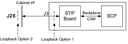
Before running the test, you must press the Emergency Stop button on the SCIM, then install a loopback connector external to the STIF board on the SCP to SCIM communication path. There are two possible configurations for the loopback connector:
-
Place the loopback connector directly on the STIF.
-
Place the loopback connector on the outside of the System Cabinet Interface.
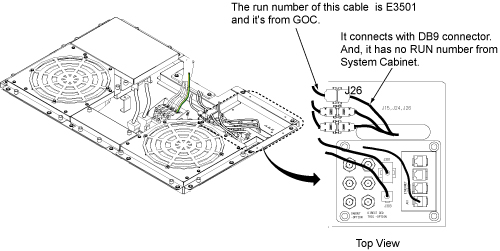
To make the loopback connector, get a DB9 connector and wire pins 1 and 2 together and pins 6 and 7 together (see Figure 2). To connect to the System Cabinet Interface, use a male connector. To connect to the STIF board, use a male connector.
Figure 2. Loopback from a DB9 Connector
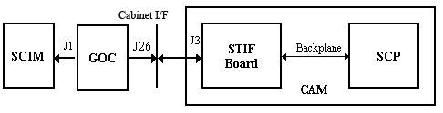
Figure 3. J26 Location on Cabinet Top
5 Block Diagram
Figure 4. SCIM External Loopback Block Diagram
6 Test Sequence
-
The SCP transmits a data packet through the SCIM serial port on the SCP board.
-
The serial data is looped back externally to the STIF board.
-
The SCP verifies that it received the same data that was sent.
Do not change the Test Options settings from the default settings unless instructed to do so by a GE Healthcare engineer. There are very few circumstances when these settings need to be changed.
7 Expected Results
After the SCIM communication path is broken to install the loopback connector, the emergency stop is triggered. Press the EMO Reset on the PDU to recover after the SCIM communication path is restored.
Output values pass or fail. In the event of failure, the details of the failure can be found in the GE System Log.
In the case of errors, click the 1st Error number to see the nature of the error. It is recommended that you view the GE System Log to view all the errors that were recorded.
If this test fails, the possible reasons are:
-
Loopback connector is defective or not installed.
-
Any cable between the loopback connector and the STIF board.
-
CAM Backplane is defective.
-
STIF board is defective.
-
SCP board is defective.
If the test passes with the loopback connector directly on the STIF, but fails with the loopback connector on the outside of the System Cabinet, then the cable from the STIF to the System Cabinet Interface or the System Cabinet Interface connector is defective.
If the test fails with the loopback connector directly on the STIF, then the problem is either the STIF board, CAM Backplane, or the SCP. Run the SCP loopback test to determine if the SCP is defective. If the SCP loopback test succeeds, check for bent or missing pins where the STIF board and SCP board connect.