I/O Data
1 Diagnostic Link
Diagnostics >> System Function >> RF >> UPM Diagnostics
Diagnostics >> Hardware Location >> System Cabinet >> CAM >> UPM Diagnostics
Figure 1. I/O Status
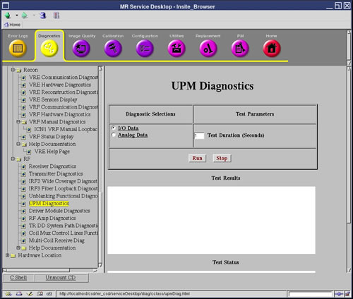
2 Purpose
The UPM Diagnostic reads the power supply information from the UPM board.
3 Components Tested
-
Chassis Power Supply
-
Chassis Power Supply Temp
-
Isolated 5 Volts
-
FPGA Initialization
-
Flash Power
-
RF NB Board
-
RF NB Cable
-
Unblank Cable
-
RF NB Negative 12 Volt
4 Requirements
No special requirements.
5 Test Sequence
-
Select the I/O Data test from the UPM Diagnostics screen.
-
Modify Test Parameters as necessary.
-
Click the Run button.
6 Expected Results
A blue color indicates a normal result. A red color indicates an error.