Grad ECC Verification
1 Diagnostic Link
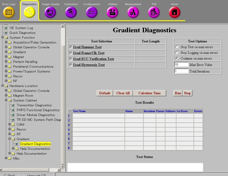
Diagnostics >> System Function >> Gradient >> Gradient Diagnostics
Diagnostics >> Hardware Location >> System Cabinet >> Gradient >> Gradient Diagnostics
Figure 1. Gradient Diagnostics screen
2 Purpose
The Gradient ECC Verification Test provides a means to diagnose hardware problems in GP3 ECC DACs and associated circuitry.
The coil is not used in the test. Gradient amplifiers are disabled during the test. Only GP3 hardware is used in the test.
3 Components Tested
-
GP3 ECC DAC
-
FRUs in test: GP3
4 Requirements
This test will automatically prompt you to verify that a TPS Reset has been recently performed.
5 Block Diagrams
None
6 Test Sequence
GP (Gradient Processor) checks for corrupted clock before running this test. The test gets aborted if it finds a corrupted clock and logs an error message.
This test checks gain and offset of ECC circuitry for each axis and compares them to ideal values. A single combination of ECC time constant and gain is loaded. A simple input step function is applied. The resulting analog output is recorded and compared to a computed ideal exponential response model. All collected data must fall within a 5% window around the ideal response for a diagnostic success. The test is performed independently on each of the three (3) axes. The Gradient ECC Verification Test fails when gain, offset, or analog output fall outside of acceptance windows.
The gradient coil is not tested during this diagnostic. Gradient amplifiers are disabled during the test. Only GP3 hardware is used in the test.
7 Expected Results
Output values are judged PASS or FAIL.
In the case of errors click the 1st Error number to see the nature of the error.
A full list of errors is available in the GE System Logs.
8 Etcetera
Click Calculate Time to get an estimate of the time it will take to run the selected diagnostics.
9 Links
None